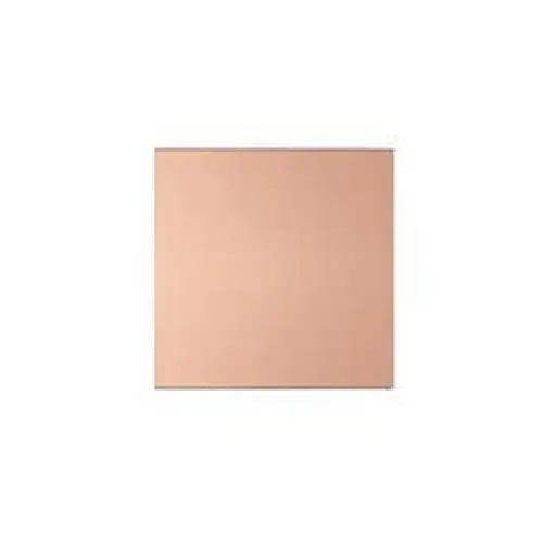
PCB Double Layer (FR-4) 10x10
PCB Double Layer (FR-4) – 10×10cm Universal Prototype Board
Overview:
This double-layer prototyping PCB is made of high-quality FR-4 fiberglass material, offering excellent durability, heat resistance, and rigidity. With a standard 10cm × 15cm size, this board is perfect for developing and soldering permanent circuits in DIY electronics, robotics, and embedded systems.
Each side features a grid of pre-drilled 1mm holes with 2.54mm spacing, compatible with most through-hole components, DIP ICs, headers, and connectors. The double-layer copper layout enables easier and more flexible routing compared to single-sided boards.
Key Features:
Board Type: Double-sided PCB
Material: FR-4 high-quality fiberglass epoxy
Hole pitch: Standard 2.54mm (0.1")
Hole diameter: ~1mm – suitable for most components
Dimensions: 10cm × 15cm
Layers: 2 copper layers (top and bottom)
Finish: Green solder mask, tinned pads
Excellent thermal stability and mechanical strength
Ideal for Arduino, ESP32, power circuits, and sensor hubs
Technical Specifications:
| Parameter | Value |
|---|---|
| Size | 10cm × 15cm |
| Layer Count | 2 (Top + Bottom) |
| Hole Pitch | 2.54mm |
| Hole Diameter | ~1mm |
| Material | FR-4 Epoxy Glass Fiber |
| Color | Green solder mask |
| Surface Finish | Tin-plated pads |
| Copper Thickness | 35µm (standard) |
| Board Thickness | ~1.6mm |
Applications:
Permanent circuit prototyping
Soldering Arduino-based circuits
Sensor arrays and breakout boards
Power distribution boards
Robotics and automation system design
Educational electronics and project prototyping
Tips for Use:
Use a fine-tip soldering iron (25W–60W) for precision
Pre-plan component placement to optimize routing
You can use both sides to reduce jumper wires
Label rows/columns with a marker for complex builds
Use standard 2.54mm pitch headers for Arduino-compatible components
Resources:
📘 Tutorial – How to Solder on Prototype PCBs:
https://youtu.be/MNxdHXwlwJM
