74266 (Quad 2-Input XNOR Gate)
🧰 Digital Logic IC – 74266 (Quad 2-Input XNOR Gate)
Overview The 74266 is a standard integrated circuit (IC) from the 74xx series of digital logic gates. Specifically, it contains four independent, 2-input XNOR (Exclusive-NOR) gates. A key characteristic of the 74266, particularly common in the 74LS266 and 74HC266 variants, is that it typically features open-collector outputs (or open-drain for CMOS versions). This output type makes it versatile for applications requiring wired-AND functionality or interfacing with different logic voltage levels, but it also means an external pull-up resistor is generally required on each output.
XNOR Logic Function An XNOR gate (also known as an Exclusive-NOR or equivalence gate) produces a HIGH (1) output only when both of its inputs are the same (both HIGH or both LOW). If the inputs are different (one HIGH and one LOW), the output is LOW (0). This is the exact opposite of an XOR gate.
Truth Table (for one XNOR gate):
Input A | Input B | Output Y (A XNOR B) |
0 (LOW) | 0 (LOW) | 1 (HIGH) |
0 (LOW) | 1 (HIGH) | 0 (LOW) |
1 (HIGH) | 0 (LOW) | 0 (LOW) |
1 (HIGH) | 1 (HIGH) | 1 (HIGH) |
Key Features
Quad 2-Input XNOR Gates: Contains four separate XNOR gates in a single package.
Logic Type: XNOR (Exclusive-NOR).
Output Type: Typically Open-Collector (TTL versions like 74LS266) or Open-Drain (CMOS versions like 74HC266). This means you generally need an external pull-up resistor from the output to VCC for the output to go HIGH.
Standard Logic Family: Part of the widely used 74xx series (e.g., 74LS266, 74HC266).
Supply Voltage: Typically operates on a +5V DC power supply (for TTL versions); CMOS versions like 74HC266 can have a wider range (e.g., 2V to 6V).
Package: Commonly available in 14-pin DIP (Dual In-line Package) and SOIC (Small Outline Integrated Circuit) packages.
Internal protection: Standard ESD (Electrostatic Discharge) protection.
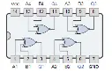
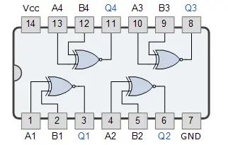
Pinout (Typical 14-pin DIP - Always confirm with specific datasheet):
The 74266 has 14 pins. The pin assignments for the four XNOR gates (A, B are inputs, Y is output) and power connections are typically as follows:
Pin 1: 1A (Input for Gate 1)
Pin 2: 1B (Input for Gate 1)
Pin 3: 1Y (Output for Gate 1)
Pin 4: 2A (Input for Gate 2)
Pin 5: 2B (Input for Gate 2)
Pin 6: 2Y (Output for Gate 2)
Pin 7: GND (Ground)
Pin 8: 3Y (Output for Gate 3)
Pin 9: 3A (Input for Gate 3)
Pin 10: 3B (Input for Gate 3)
Pin 11: 4Y (Output for Gate 4)
Pin 12: 4A (Input for Gate 4)
Pin 13: 4B (Input for Gate 4)
Pin 14: VCC (Positive Power Supply, e.g., +5V)
Important Note on Open-Collector Outputs: Because the outputs are open-collector, when the output of a gate is supposed to be HIGH, the transistor inside is essentially "off," leaving the output floating (high impedance). To actually achieve a HIGH logic level, you must connect a pull-up resistor (typically 1kΩ to 10kΩ) from the output pin to the VCC power supply. When the output is LOW, the transistor turns "on," providing a low-impedance path to ground.
Applications
Equality Comparators: Directly used to check if two binary inputs are equal (output HIGH if equal, LOW if unequal).
Error Detection and Correction (Parity Checkers): Used in systems to detect if an odd or even number of bits have changed, crucial for data integrity.
Digital Comparators: Can be combined to compare larger binary numbers.
Selectable Inverters/Buffers: When one input is tied HIGH, the XNOR gate acts as an inverter. When one input is tied LOW, it acts as a buffer.
Controlled Inversion: Can be used to conditionally invert a signal.
Pattern Generation/Recognition: Useful in sequences where input patterns need to be matched.
Arithmetic Operations: Can be part of more complex adder/subtractor circuits.