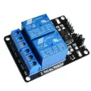
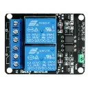
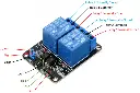

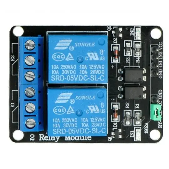

Relay Module 2 channels 5V
🔁 2-Channel 5 V Relay Module – SPDT (Low-Level Trigger)
Overview
This 2-channel relay module allows your microcontroller (Arduino, ESP32, Raspberry Pi, etc.) to control two high-voltage or high-current loads independently. Each channel uses a standard 5 V DC coil, supports 10 A switching at 250 VAC / 30 VDC, and includes onboard optocouplers and indicator LEDs for improved isolation and feedback
Key Features
Coil voltage: 5 V DC (low-level trigger)
Optoisolated inputs: Optional jumper between VCC and JD-VCC
Contact rating: 10 A @ 250 VAC / 30 VDC per channel
Active LOW inputs: Module activates when input pin is LOW
Driver current per channel: ~15–20 mA
PCB form factor: Compact ~50 × 38 mm with mounting holes
Visual indicators: LEDs light up when relays activate
Technical Specifications
| Parameter | Value |
|---|---|
| Input Voltage (Coil) | 5 V DC |
| Input Current | ~15–20 mA per channel |
| Switching Voltage | 250 VAC / 30 VDC |
| Max Switching Current | 10 A per relay |
| Trigger Type | LOW-level (0–2 V to activate) |
| Opto-isolation | Yes (via JD-VCC jumper option) |
| Dimensions | ~50 × 38 × 18 mm |
| Communication Signals | IN1, IN2 (digital), VCC, GND, JD-VCC |
| Mounting Holes | Yes (~3 mm diameter) |
Wiring with Arduino UNO
Power Connection:
VCC → 5 V (Arduino)
GND → GND
Keep or remove JD-VCC jumper depending on isolation needs
Control Signals:
IN1, IN2 → Arduino GPIO pins
Set pins LOW to activate corresponding relay
Load Wiring:
Each relay channel: COM, NO, NC screw terminals
Use NO for normally-off operation or NC for normally-on setup
💡 Ensure common ground when sharing power; use separate power for JD-VCC if opting for isolation
Applications
Home automation (lights, fans, pumps)
Controlling AC mains or DC motors
Robotics and IoT devices
Electrical isolation for sensitive electronics
DIY and industrial automation
✅ Resources
🎥 YouTube Tutorial:
“How to control a 2-channel 5V relay module with Arduino” – Covers wiring, jumper usage, code setup and safety precautions components101.com+14youtube.com+14sainsmart.com+14