Transistors IRF9540 P‑Channel Power MOSFET
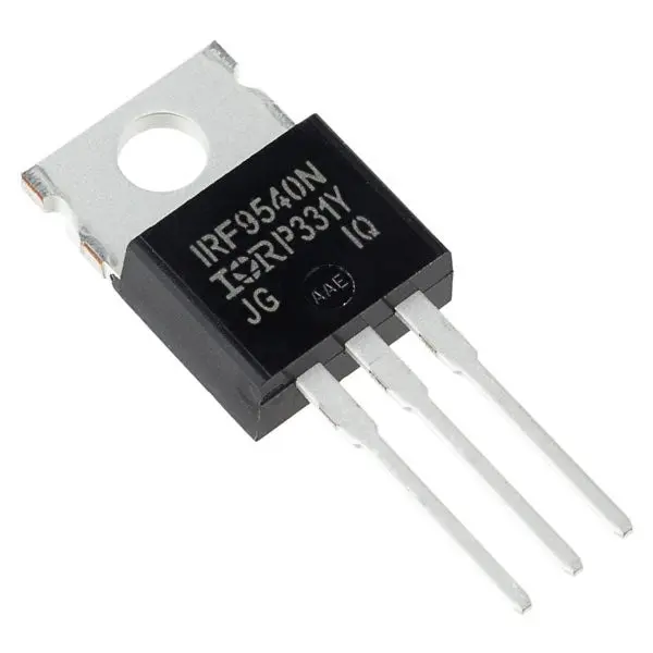
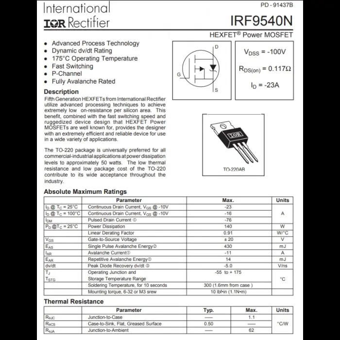
IRF9540 – P‑Channel Power MOSFET (TO‑220)
Overview:
The IRF9540 is a high-performance P‑Channel MOSFET in a TO‑220 package, designed for switching and amplification in high-side load control, converters, and power management. It supports continuous currents of -100 V and -19 A, as well as pulses of -72 A, making it suitable for automotive, industrial, and battery-powered systems.
Key Features:
P‑Channel enhancement-mode MOSFET
Drain‑Source Voltage (V<sub>DS</sub>) = -100 V
Continuous Drain Current = -19 A @ 25 °C
Pulse Drain Current = -72 A
Low R<sub>DS(on)</sub> ≈ 0.20 Ω @ V<sub>GS</sub> = -10 V
Fast switching, repetitive avalanche rated
TO‑220 package with low thermal resistance
Operating junction up to 175 °C
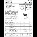
Technical Specifications:
| Parameter | Value |
|---|---|
| V<sub>DS</sub> | -100 V |
| V<sub>GS</sub> | ±20 V |
| Continuous I<sub>D</sub> | -19 A @ 25 °C, -13 A @ 100 °C |
| Pulsed I<sub>D</sub> | -72 A |
| R<sub>DS(on)</sub> | 0.20 Ω @ V<sub>GS</sub> = -10 V |
| Q<sub>g</sub> (Total Gate Charge) | 61 nC |
| EAS (Single Avalanche) | 640 mJ |
| Power Dissipation (TC = 25 °C) | 150 W |
| Package | TO‑220AB, metal-tab heater sinkable |
| Temperature Range | –55 °C to +175 °C |
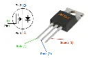
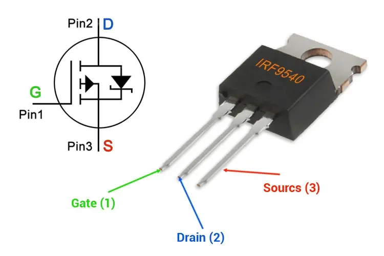
Pinout (Front View, TO‑220):
CopyEditTab = Drain Pin 1: Gate Pin 2: Drain Pin 3: Source (Body diode internal)
How It Works:
Driving a P‑Channel MOSFET like the IRF9540 requires pulling the Gate lower than the Source (e.g., Source = +12 V, Gate = 0 V → MOSFET ON). When the Gate is near Source voltage, it turns OFF. Ideal for high-side switching. vishay.com+1digikey.com+1eandc.ru+2digikey.com+2vishay.com+2components101.com+1components101.com+1
Wiring Example – High‑Side Power Switching:
Source (Pin 3) → +12 V
Drain (Pin 2) → Load → Ground
Gate (Pin 1) → Logic output (e.g., Arduino) through 10 kΩ pull-up resistor to +12 V; gate driven to 0 V to turn ON, 12 V to turn OFF.
Don’t forget:
Use a gate resistor (e.g., 100 Ω) to prevent oscillations
Include a flyback diode across inductive loads (motors, solenoids)
Ensure Source and Gate voltage difference ≤ 20 V
Applications:
High-side switching of motors and solenoids
Battery-powered systems requiring positive-side control
Power conversion circuits and amplifiers
Automotive 12 V/24 V systems
Load balancing and voltage regulation
Resources:
📄 Datasheet PDF (Vishay Siliconix): Download PDF docs.cirkitdesigner.comcircuits-diy.comdatasheet4u.com+4vishay.com+4digikey.com+4
📘 IRF9540 Diagrams & Specs (Components101): Pinout, resistance, and drive info latinafy.com+14components101.com+14components101.com+14
🛠️ Arduino High‑Voltage Driving Example: Step‑by‑step guide using IRF9540 in an Arduino-powered inverter circuits-diy.com+1forum.allaboutcircuits.com+1
🎥 YouTube Tutorial – IRF9540 in Action:
High‑Side Motor Control Using P‑Channel IRF9540